GOST R IEC 60285-2002
Group E51
STATE STANDARD OF THE RUSSIAN FEDERATION
Alkaline batteries and batteries
SEALED CYLINDRICAL NICKEL-CADMIUM BATTERIES
Alkaline secondary cells and batteries.
Sealed nickel-cadmium cylindrical single cells
OKS 29.220.30
OKP 34 8230
Date of introduction: 2003-07-01
Preface
1 DEVELOPED AND SUBMITTED BY the Technical Committee for Standardization TC 044 "Accumulators and Batteries"
2 ADOPTED AND PUT INTO EFFECT by the Resolution of the State Standard of Russia dated December 25, 2002 No. 509-st
3 This standard is the complete authentic text of the international standard IEC 60285 (1999), version 3.2 "Alkaline batteries and accumulators. Sealed nickel-cadmium cylindrical batteries"
4 INSTEAD OF GOST R IEC 285-97
1 General Provisions
1.1 Scope
This standard establishes technical requirements and testing methods for sealed nickel-cadmium cylindrical batteries (hereinafter referred to as batteries) suitable for operation in any spatial position.
The standard also establishes specific technical requirements and test methods for batteries intended to operate in long-term charge mode at elevated temperatures.
1.2 Normative references
This standard contains references to the following standards:
GOST 8711-93 (IEC 51-2-84) Direct-acting and auxiliary analog indicating electrical measuring instruments. Special requirements for ammeters and voltmeters
GOST 30012.1-2002 (IEC 60051-1-97) Direct-acting analog indicating electrical measuring instruments and their auxiliary parts. Part 1. Definitions and basic requirements common to all parts
GOST R IEC 86-1-96 Primary batteries. Part 1. General provisions
GOST R IEC 86-2-96 Primary batteries. Part 2. Specification sheets
GOST R 50779.71-99 (ISO 2859-1-89) Statistical methods. Sampling inspection procedure by attribute. Part 1. Lot-by-lot sampling plans based on acceptable quality level (AQL)
GOST R 51371-99 Test methods for resistance to mechanical influences of machines, devices, and other technical products. Impact tests
1.3 Definitions
The following terms and definitions are used in this standard:
1.3.1 Sealed battery: A battery that remains sealed and does not allow gas or electrolyte to escape when operating under the charging conditions and temperatures specified by the manufacturer. The battery may be equipped with a safety device to prevent dangerously high internal pressure.
The battery does not require additional electrolyte filling and is designed to operate in its original sealed state throughout its entire service life.
1.3.2 Nominal Voltage: Battery voltage equal to 1.2 V.
1.3.3 nominal capacity: Amount of electricity![]() (Ah) specified (established) by the manufacturer, which the battery can deliver at a temperature of 20 °C and a 5-hour discharge mode to a final voltage of 1.0 V after charging, storage and discharge under the conditions specified in section 4.
(Ah) specified (established) by the manufacturer, which the battery can deliver at a temperature of 20 °C and a 5-hour discharge mode to a final voltage of 1.0 V after charging, storage and discharge under the conditions specified in section 4.
1.4 Measuring instruments
Measuring instruments used in testing must ensure the required measurement accuracy. Instruments must be regularly calibrated to ensure testing meets the accuracy class specified in this standard.
1.4.1 Voltage measurement
To measure voltage, voltmeters of accuracy class 0.5 or higher must be used (see GOST 30012.1, GOST 8711 or IEC 485 [1]).
The voltmeter must have a resistance of at least 10 kOhm/V.
1.4.2 Current measurement
To measure current, ammeters of accuracy class 0.5 or higher must be used (see GOST 30012.1, GOST 8711 or IEC 485 [1]).
The same accuracy class must be present in a kit consisting of an ammeter, a shunt and wires.
1.4.3 Temperature measurement
To measure temperature, use a thermometer with a graduated or digital scale with a division value no greater than 1°C. The absolute accuracy of the device must be 0.5°C or higher.
1.4.4 Time measurement
Time must be measured with an error of 0.1% or higher.
2 Designation and marking
2.1 Designation of batteries
Sealed nickel-cadmium cylindrical batteries must be designated by the letters KR, followed by the letters L, M, H or X, indicating the battery type depending on their main discharge mode with direct current:
L — long-term (no more than 0.5![]() A);
A);
M — medium (from 0.5![]() up to 3.5
up to 3.5![]() A);
A);
H - short (from 3.5![]() up to 7
up to 7![]() A);
A);
X - extra short (from 7![]() up to 15
up to 15![]() A),
A),
followed by two groups of numbers separated by a slash.
For a battery designed to operate in long-term charge mode at elevated temperatures, the letter T is added to the designation between L, M or H and two groups of numbers.
The first two digits (the first group of digits) indicate the maximum diameter of the battery in millimeters, expressed as a whole number or rounded to a whole number.
The two digits (the second group of digits) after the oblique line indicate the maximum height of the battery in millimetres, expressed as a whole number or rounded to a whole number.
If the manufacturer designs the battery with dimensions and tolerances that ensure interchangeability with primary cells, the primary cell designation may also be marked on the battery.
An example of the symbol for a sealed nickel-cadmium cylindrical battery with a long discharge mode, 33 mm in diameter and 61.5 mm in height:
KRL 33/62
The same applies to a battery operating in a long-term charge mode at an elevated temperature and interchangeable with a primary R20 element:
KRLT 33/62, KR20
Note: The designation of battery types L, M, H or X indicates the recommended basic discharge mode, but does not limit the use of these batteries in other discharge modes.
2.2 Battery terminals
2.2.1 Terminalless (CF) batteries
Batteries without connecting terminals are designated by the letters CF (see 2.2.3, Figure 1).
Example of a symbol for a battery without connecting terminals:
KRH 33/62 CForKRMT 33/62 CF
2.2.2 Batteries with connecting terminals on the cover and along the body (NN)
Batteries intended to be assembled into a set so that they form batteries of different voltages may be placed next to each other in the same direction.
With this configuration, one connecting terminal must be connected to the battery cover (positive pole), and the other to the battery case along its cylindrical wall (negative pole), with both terminals located in the same plane, unless otherwise specified by the consumer (see 2.2.3, Figure 2). In this case, the letters HH (cover-cover) are added to the battery designation.
An example of a battery symbol with connecting terminals on the cover and along the body:
KRH 33/62 ННorKRMT 33/62 NN
2.2.3 Batteries with connecting terminals on the cover and bottom of the case (HB)
Batteries intended for assembly into a kit can be located next to each other, attached with the lid of one battery to the bottom of the case of another battery.
With this arrangement, one connecting terminal should be connected to the battery cover (positive pole), and the other to the bottom of the battery case (negative pole), with both terminals positioned parallel and in opposite directions, unless otherwise specified by the consumer (see Figure 3). In this case, the letters HB (cover-bottom) are added to the battery designation.
An example of a battery symbol with connecting terminals on the cover and bottom of the case:
KRH 33/62 HBorKRMT 33/62 HB
Figure 1 - Batteries without terminals KR . . . CF
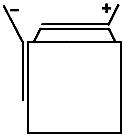
Figure 2 — Cover-to-cover connection KR . . . NN
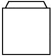
Figure 2 — Cover-to-cover connection KR . . . NN
Figure 3 — Connection cover - bottom of the KR housing . . . HB

2.3 Marking
A terminalless (CF) battery must be durably marked with the following information (unless otherwise specified by the consumer):
— battery name — sealed, rechargeable nickel-cadmium;
— battery designation (according to 2.1);
- nominal capacity;
— nominal voltage;
— recommendations on the mode and duration of charging or pre-charging current for type T batteries;
— polarity;
— year and quarter of manufacture (can be coded);
—name or designation of the manufacturer or supplier.
Note: In most cases, batteries with LV or HB terminals are assembled as batteries and do not have a label; in this case, the battery must be marked in accordance with 2.1.
3 Dimensions
The dimensions of the batteries must correspond to those indicated in Figure 4 and Table 1.
Figure 4 - Cylindrical battery in a case, interchangeable with primary cells
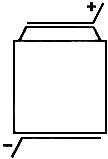
Table 1 shows the dimensions of batteries in cases that are interchangeable with primary cells.
Table 1 - Dimensions of batteries in cases interchangeable with primary cells
| Designation* | Corresponding primary element** according to GOST R IEC 86-1 | Dimensions |
| KR03 | R03 | |
| KR6 | R6 | According to GOST R IEC 86-2 |
| KR14 | R14 | |
| KR20 | R20 | |
| _______________* According to GOST R IEC 86-1. | ||
| ** In some countries these are elements of types AAA(R03), AA(R6), C(R14), D(R20). | ||
Table 2 shows the dimensions of other batteries in cases, except for those interchangeable with primary cells.
Table 2 - Dimensions of batteries in cases (excluding connecting terminals)
| Dimensions in millimeters | ||||
| Designation* | Diameter |
Height |
||
| Nomin. | Prev. off | Nomin. | Prev. off | |
| KR11/45 | 10.5 | 44.5 | ||
| KR12/30 | 12.0 | 30.0 | ||
| KR15/18 | 14.5 | 17.5 | ||
| KR15/30 | 14.5 | 0-0.7 | 30.0 | 0-1.5 |
| KR15/51 | 14.5 | 50.5 | ||
| KR17/18 | 17.0 | 17.5 | ||
| KR17/29 | 17.0 | 28.5 | ||
| KR17/43 | 17.0 | 43.0 | ||
| KR17/50 | 17.0 | 50.0 | ||
| KR23/27 | 23.0 | 26.5 | ||
| KR23/34 | 23.0 | 34.0 | 0-1.5 | |
| KR23/43 | 23.0 | 0-1.0 | 43.0 | |
| KR26/31 | 25.8 | 31.0 | ||
| KR26/50 | 25.8 | 50.0 | ||
| KR33/44 | 33.0 | 44.0 | 0-2.0 | |
| KR33/62 | 33.0 | 61.5 | ||
| KR33/91 | 33.0 | 91.0 | 0-2.5 | |
| KR44/91 | 43.5 | 0-2.5 | 91.0 | |
| _______________* The letters KR are followed by the letters L, M, H or X and LT, MT or HT respectively (see 2.1). | ||||
4 Electrical tests
The charge and discharge currents during tests according to 4.1-4.8 should be set based on the nominal capacity of the battery.
During all tests except 4.7, there should be no electrolyte leakage.
4.1 Charging method
Charging preceding various discharge modes (unless otherwise specified in this standard) is carried out at an ambient temperature of (20±5) °C with a constant current of 0.1![]() And within 16 hours.
And within 16 hours.
Before charging, the battery must be discharged at an ambient temperature of (20±5) °C with a constant current of 0.2![]() And up to the final voltage of 1.0 V.
And up to the final voltage of 1.0 V.
4.2 Discharge characteristics
The discharge characteristics of batteries should be checked in the following sequence.
4.2.1 Discharge characteristic at 20 °C
The battery must be charged in accordance with 4.1. After charging, the battery must be kept for at least 1 hour, but no more than 4 hours, at an ambient temperature of (20±5)°C. The battery must then be discharged using a constant current in accordance with Table 3 at the same temperature. The discharge duration must be no less than that specified in Table 3.
Table 3 - Discharge characteristics at 20 °C
| Discharge mode | Minimum discharge time for battery types | ||||
| Current, A | Final voltage, V | L/LT | M/MT | H/HT | X |
| 0.2 |
1.0 | 5 hours | 5 hours | 5 hours | 5 hours |
| 1.0 |
42 min | 48 min | 54 min | ||
| 5.0 |
0.8 | — | 6 min | 9 min | |
| 10.0 |
0.7 | — | — | 4 min | |
| _______________* Five charge-discharge cycles are permitted. The test may be terminated if the discharge duration is reached before the fifth cycle. | |||||
| **Before the discharge test with 5.0 currents |
|||||
4.2.2 Discharge characteristic at minus 18 °C
The battery must be charged in accordance with 4.1. After charging, the battery must be kept for at least 16 hours, but no more than 24 hours, at an ambient temperature of -18±2°C. The battery must then be discharged using a constant current in accordance with Table 4 at the same temperature. The discharge duration must be no less than that specified in Table 4.
Table 4 — Discharge characteristics at minus 18 °C
| Discharge mode | Minimum discharge time for battery types | ||||||
| Current, A | Final voltage, V | L/LT | M | MT | N | NT | X |
| 0.2 |
1.0 | 2 hours | 3 hours | 2 hours | 3 hours | 2 hours | 4 hours |
| 1.0 |
0.9 | 15 min | 10 min | 30 min | 20 min | 36 min | |
| 2.0 |
0.8 | — | — | — | 9 min | 6 min | 13 min |
| 3.0 |
— | — | 7 min | ||||
| _______________* Before the discharge test with currents of 2.0 |
|||||||
4.3 Charge preservation
The battery must be tested for charge retention using the following test.
After charging in accordance with 4.1, the battery must be stored (maintained) in an open circuit for 28 days. The average ambient temperature should be (20±2) °C; however, short-term deviations of ±5 °C are allowed during storage.
Then the battery must be discharged under the conditions specified in 4.2.1 with a discharge current of 0.2![]() A.
A.
The discharge duration after 28 days of storage should be at least 3 hours 15 minutes.
4.4 Operating time
4.4.1 Operating time in cycles
Before testing, the battery must be discharged with a constant current of 0.2![]() And up to the final voltage of 1.0 V.
And up to the final voltage of 1.0 V.
The test (regardless of the battery type) is carried out at an ambient temperature of (20±5) °C.
Charging and discharging must be carried out with constant current in cycles in the modes specified in Table 5. If necessary, forced air cooling of the battery must be used during testing to prevent its casing temperature from rising above 35 °C.
Note: The actual battery case temperature is determined by the battery design and not by the ambient temperature.
Table 5 — Operating time in cycles
| Cycle number | Charging mode | Storage time in charged state | Discharge mode | ||
| Current, A | Duration | Current, A | Duration | ||
| 1 | 0.1 |
16 hours | 0.25 |
||
| 2-48 | 0.25 |
3 hours 10 minutes | — | 0.25 |
2 hours 20 minutes |
| 49 | 0.25 |
3 hours 10 minutes | 0.25 |
Up to final voltage of 1.0 V* | |
| 50 | 0.1 |
16 hours | 1-4 hours | 0.2 |
|
| _______________* It is permissible to keep batteries in an open circuit after the end of discharge at the 50th cycle, so that by the beginning of the 51st cycle it is no more than 14 days. | |||||
| A similar procedure can be applied to the 100th, 150th, 200th, 250th, 300th, 350th cycles. | |||||
Cycles 1-50 should be continued until the discharge duration on any cycle multiple of 50 is less than 3 hours. The next cycle should be carried out in the 50th cycle mode.
The test is considered complete if the discharge duration over two consecutive cycles is less than 3 hours.
The number of cycles at the end of the tests must be no less than:
400 — for batteries of types L, M, H and X;
50 — for batteries of LT, MT and HT types.
To speed up the cycle life testing or when using this test to determine the feasibility of actual application, the modes specified in Tables 5a and 5b may be used.
Table 5a — Operating time in cycles for batteries of types H and X
| Charging mode | Storage time in charged state | Discharge mode | ||||
| Cycle number | Current, A | Duration, h | Current, A | Duration | Total duration, including subsequent break, min | |
| 1 | 0.1 |
16 | 30 min | 1.0 |
||
| 2-48 | 0.3 |
4 | 30 min | 1.0 |
Up to final voltage of 1.0 V | 90 |
| 49 | 0.3 |
4 | 24 hours | 1.0 |
||
| 50 | 0.1 |
16 | 1-4 hours | 0.2 |
-* | |
| _______________* It is permissible to leave the batteries in an open circuit after the end of discharge at the 50th cycle in order to begin the next 51st cycle at a convenient time. A similar procedure can be applied to the 100th, 150th, 200th, 250th, 300th, and 350th cycles. | ||||||
Cycles 1-50 continue until the discharge duration to a final voltage of 1.0 V on any cycle multiple of 49 becomes less than 30 minutes or on any subsequent 50th cycle becomes less than 3 hours.
The number of cycles must be at least 400.
Table 5b — Operating time in cycles for batteries of type X
| Charging mode | Storage time in charged state | Discharge mode | ||||
| Cycle number | Current, A | Duration, h | Current, A | Duration | Total duration, including subsequent break, min | |
| 1 | 0.1 |
16 | 30 min | 5.0 |
Up to final voltage of 0.8 V | |
| 2-48 | 1.0 |
1 | 30 min | 5.0 |
42 | |
| 49 | 1.0 |
1 | 24 hours | 5.0 |
||
| 50 | 0.1 |
16 | 1-4 hours | 0.2 |
Up to a final voltage of 1.0 V | -* |
| _______________* It is permissible to leave the batteries in an open circuit after the end of discharge at the 50th cycle in order to begin the next 51st cycle at a convenient time. A similar procedure can be applied to the 100th, 150th, 200th, 250th, 300th, and 350th cycles. | ||||||
Cycles 1-50 continue until the discharge duration to a final voltage of 0.8 V on any cycle multiple of 49 becomes less than 5 minutes or on any subsequent 50th cycle becomes less than 3 hours.
The number of cycles must be at least 400.
4.4.2 Long-term charge operation
4.4.2.1 Operating time with long-term charge for batteries of types L, M, H and X
Before testing, the battery must be discharged with a constant current of 0.2![]() And up to the final voltage of 1.0 V.
And up to the final voltage of 1.0 V.
The test is carried out at an ambient temperature of (20±5) °C.
Charging and discharging are carried out with direct current in the modes specified in Table 6. The discharge duration after completion of four consecutive cycles should be at least 3 hours.
If necessary, forced air cooling of the battery should be used during testing to prevent the temperature of its casing from rising above 25 °C.
Table 6 - Operating time with long-term charging
| Cycle number | Charging mode | Discharge mode* | ||
| Current, A | Duration, days | Current, A | Duration | |
| 1 | 0.05 |
91 | 0.2 |
|
| 2 | 0.05 |
91 | 0.2 |
Up to a final voltage of 1.0 V |
| 3 | 0.05 |
91 | 0.2 |
|
| 4 | 0.05 |
91 | 0.2 |
|
| _______________* Discharge is carried out immediately after completion of charging. | ||||
4.4.2.2 Operating time with long-term charge for batteries of types LT, MT or NT
The test is carried out in three stages in accordance with Table 7.
The tests consist of:
— checking the efficiency of the charge;
— aging period — aging for 6 months at a temperature of 70 ° C.
Note: A temperature of 70°C is estimated to simulate a long-term charge for 4 years at a temperature of 40°C;
- final check of charging efficiency to monitor batteries after the aging period.
Before testing, the battery must be discharged with a constant current of 0.2![]() And up to the final voltage of 1.0 V and maintained for at least 16 hours and no more than 24 hours at an ambient temperature of (40±2) °C.
And up to the final voltage of 1.0 V and maintained for at least 16 hours and no more than 24 hours at an ambient temperature of (40±2) °C.
The battery must be charged and discharged with constant current in accordance with Table 7, including the holding time at ambient temperatures of (40±2) °C and (70±2) °C, respectively.
Discharge mode A or B (see Table 7) is selected depending on the user's requirements. Discharge is performed immediately after charging is complete.
After the first test for charging efficiency at a temperature of 40 °C, the battery must be kept for at least 16 hours and no more than 24 hours at a temperature of (70±2) °C.
If necessary, during the 6 months of aging at 70°C, measures must be taken to prevent the battery case temperature from rising above 75°C.,Why should forced air cooling be used?
Note: The actual battery case temperature is determined by the battery design and not by the ambient temperature.
The discharge duration for three cycles at 70°C should be recorded.
Electrolyte leakage is not allowed during testing.
After the end of the aging period, the batteries must be kept for at least 16 hours and no more than 24 hours at an ambient temperature of (40±2)°C. Three cycles of the initial charging efficiency test shall then be repeated at 40°C in accordance with the conditions given in Table 7. The discharge duration shall not be less than that specified in Table 7.
Table 7 — Operating time with long-term charging for batteries of types LT, MT and NT
| Cycle number | Ambient temperature, °C±2 °C | Charging mode | Discharge mode | Minimum discharge duration for the mode | |||
| A* | IN** | ||||||
| Current, A | Duration, days | Current, A | Duration | A* | IN** | ||
| 1 | 2 | Not standardized | |||||
| 2 | 40 | 0.05 |
1 | 0.2 |
Up to a final voltage of 1.0 V | 3 hours 45 minutes | 42 min |
| 3 | 1 | ||||||
| 4 | 60 | ||||||
| 5 | 70 | 0.05 |
60 | 0.2 |
Up to a final voltage of 1.0 V | Not standardized | |
| 6 | 60 | ||||||
| 7 | 2 | Not standardized | |||||


